Laddar...
Shaft Dam at Malmön
At the mentioned mine on Malmön, which lies very close to the lakeshore, the approximately 15-foot-deep soil layer above the bedrock consisted mainly of gravel and rounded stones, making the ground permeable. As a result, the mine became heavily waterlogged.
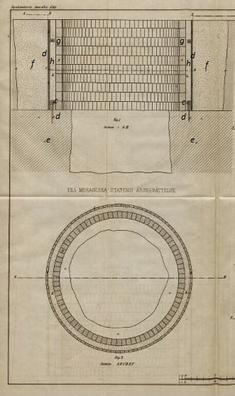
To remedy this, or in other words to keep the lake water out, a dam was constructed of the type shown in Plate IX, Figures 1 and 2.
Around the shaft, the natural gravel layer was first removed along the lines a–a, after which the rock surface was levelled. A timber casing (b–b) made of tightly joined planks was then installed.
The planks were nailed to circular rings c–c made of planks, of which the lowest was fixed to the rock with iron bolts (d–d).
Between the bedrock (e–e) and the casing, the space was sealed with tarred oakum, after which the cavity f was filled with fine sand or so-called “pinnmo.”
To provide additional resistance against the pressure of the surrounding soil and to protect the wooden casing from decay, a second inner casing (g–g) made of slag bricks was built concentrically inside the first.
The space between the two was filled at the bottom with rammed clay and above that with pinnmo.
The dam constructed in this manner has since its completion proven fully effective in achieving its purpose, namely to keep the water out, which previously had both hindered mining operations and caused additional costs for pumping.
Source: Jernkontorets Annaler, 1865
Transcription: TN, December 2024
Wire-Rope Pumping Transmission between Långban and Malmön
In 1866, a 7,500-foot-long wire-rope transmission line was installed between the waterwheel at the Långban mines and Malmön in Lake Långban.
The work was supervised by L. M. Larsson, an apprentice in the Mechanical Department of Jernkontoret.
The 17-strand wire ropes (No. 11) were suspended over land in roughly the same way as the rod system at Nordgruvan, described in Jernkontorets Annaler 1862.
Where the line crossed the lake, piles driven into the lakebed supported the suspension posts in shallow water, while in deeper water floating logs anchored with wire ropes supported the moving cable.
To reduce tension in the cable, the mechanism was designed so that the movement of the cable was twice the stroke of the driving crank, while the pump stroke at the mine was half the cable movement.
Thus, power was converted into speed at the waterwheel, and speed back into power at the mine.
The distance between the suspension posts was 90–100 feet.
Source: Jernkontorets Annaler, 1866
Transcription: TN, December 2024