Laddar...
The Limtjärn Mining Field – Technical Solutions at the Mines
At the Limtjärn mining field there are several mines, but three of them contain particularly interesting technical solutions. At Nyårsgruvan there was a wire-driven pumping transmission (“iron-wire pumping system”), at Limkärnsgruvan a ventilation machine, and at Bergmästargruvan an unusual method of earth removal in unstable ground conditions before sinking a shaft down to the bedrock. The following is a description of these technical solutions.
Nyårsgruvan
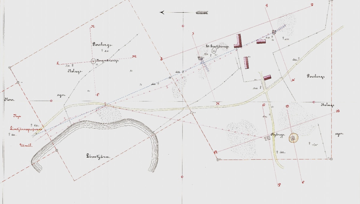
In the Annals of the Swedish Ironmasters’ Association (Jernkontoret) from 1866 it is reported that L.M. Larsson constructed a 600-metre-long pumping transmission line to Nyårsgruvan. Instead of wooden rods, an iron wire rope was used to transmit the power to the mine. The wire-driven system was connected to the existing pumping system at Nya Limkärnsgruvan. Figure 4 shows the route of the wire transmission to Nyårsgruvan.
Jernkontoret Annals 1866.
Limtjärnsgruvan
In 1862, under the direction of L.M. Larsson, a ventilation machine (“Luft-vexlings-machin”) was put into operation at Limkärnsgruvan. It was powered by the existing pumping system and removed foul air from the mine. Figure 6 shows the ventilation machine.
The machine had a simple and reliable construction with few moving parts. It was driven by the main pumping rod (marked k), which moved up and down. The rod extended down into the mine shaft and was connected to each pump installation. When the inner cylinder (f) was lifted, a vacuum was created in the cylinder and valve (d) opened, drawing the foul air through pipe (a), which led down into the mine, into the cylinder. When the rod reversed and the cylinder moved downward, valve (d) closed and valve (g) opened, forcing the foul air out of the cylinder. The cylinders b, open at the top, and f, open at the bottom, were filled with water as shown in Figure 6.
Jernkontoret Annals 1855.
Bergmästargruvan
The mine received the necessary power from the pumping and hoisting turbine at Skribotjärn (Figure 2). The pumping and hoisting transmission lines that had already been drawn to Nya Limtjärnsgruvan were extended by approximately 300 metres.
Extract from the Mining Reports
In Extracts from the Reports on the Mines of the Filipstad Mining District the following can be read about Bergmästargruvan:
• 1865: A newly reopened mine that was found to contain an ore vein about one fathom in width. In some places the ore occurs in limestone and is fine and clean, though not in particularly large quantity. 1880 barrels of ore were hoisted.
• 1866: The shaft was sunk along a narrow but clean ore vein which appeared to diminish toward the end of the year. During the year 1751 barrels of ore were obtained.
• 1867: The mine was not worked during the year.
Earth Removal at Bergmästargruvan
The following is a transcription of a document found in the Jernkontoret Annals, 1865, describing how “earth removal” was carried out at Bergmästargruvan.
Figures 3 and 4 show a structure for earth removal, or a so-called timber frame at Byggmästaregrufvan. From a previously excavated shaft it was known that the soil layer was approximately 40 feet (≈12 m) deep, and that 15 to 20 feet below the surface it was very loose and furthermore intersected by water veins.
To reach the bedrock through soil layers of such characteristics, the following method was used: — First, the earth was excavated from the upper, firmer layer to a depth of 18 feet, and into this was inserted a tube made of carved planks 30 feet long, which on the inside were supported by inserted plank rings.
As excavation progressed, the planks were driven down one by one in sequence with large sledgehammers, so that their lower ends always remained at the same depth as the bottom of the shaft. This procedure continued until the upper ends of the planks reached ground level. Inside the first tube, a second tube with its rings was then inserted and driven down in the same manner as before, until its lower end reached the bedrock.
Structures for such purposes had previously usually been made square or octagonal and of horizontal timber, but for obvious reasons the round shape provides greater strength, while driving down the standing timber significantly facilitates construction, especially when passing through looser soil layers.
(The diameter of the outer timber cylinder is approximately 7.5 meters.)
The guides for the hoisting rope
Fig. 5(5) shows one of the guides for the hoisting rope installed at the same mine. In order to provide space for the cast-iron pulley and the mounting of its axle, the post is split at the upper end, and its side pieces widened by means of the cross-beam and the top plate, while they are at the same time held together by iron rings. Guide irons prevent the rope from slipping down between the pulley and the side pieces.
Fig. 5(6) shows the pulley in cross-section. It runs on a steel axle, turned on a lathe, with one end made square so that it can be held firmly in position. In the centre of the pulley a layer of Babbitt metal is cast in order to reduce wear and ensure smooth running.
An oil hole is also provided in the middle of the hub. The thin casting becomes quite hard during the casting process and should therefore resist wear from the rope better than is usually the case. The rope itself may also be protected from such wear by the easy running of the pulley.
Through the links attached to the Annals of Jernkontoret, you can find the original drawing and the accompanying descriptions.
At the far left of the original drawing from Bergmästargruvan a shaft sealing structure on Malmön in Lake Långban is shown. If you wish to read about the project on Malmön, a link is attached.